Precise cooling for maximum process reliability
Variable Control Systems
Monitoring and control from the consumer to the production line...
The variable multi-loop control system with integrated electronic flow and temperature measurement enables complete control of production processes as well as monitoring the energy consumption of individual cooling circuits or an entire cooling water system. By monitoring individual process parameters with freely definable alarm limits and correspondingly regulating the flow rate of individual cooling water circuits, the system achieves advantages in process reliability and thus also in the quality of the manufactured products. The recording and archiving of individually defined process parameters also enables the reproducibility of recurring production processes. Central data acquisition in a cloud allows current and historical consumption data to be clearly displayed on a dashboard. The energy costs of individual consumers are thus easily understandable and visible in detail.
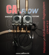
Multizone Control System CFX M7 4.0
Enables energy cost savings of up to
30%
by optimizing the required flow rate.
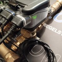
The CALFLOW CFX M7 4.0 is a multi-zone cooling water control system specifically designed for cooling applications in the manufacturing industry. The system's design is "open," meaning it is scalable (1 to X control loops) and can be gradually adapted to the flow rate requirements in the range from 20 to 59,000 l/h by installing appropriate valve sizes. A multifunctional, high-precision actuator controls a pressure-independent control valve for each cooling water circuit to prevent oversupply of the respective cooling zone and ensure constant initial conditions at all times. The digital control valve, in combination with an additional vortex flow sensor and a versatile control system, opens up new possibilities for contributing to greater process reliability and energy efficiency. Two PT1000 temperature sensors, one in the supply and one in the return, together with the flow rate measured by the vortex flow sensor, provide the most important input parameters for the control process.
In addition to controlling the cooling water flow in tools and molds, the system can also be adapted for temperature control and heating applications for a wide variety of end devices. For example, fan coil units, chilled beams, intercoolers/heaters, heated/chilled ceilings, and others can be operated by controlling the hot or cold conveying medium through the system. Expanding to the changeover version and a 4-pipe system, it is even possible to switch from a cooling function to a heating function without any modifications. A "blow-out function" can also be implemented this way.
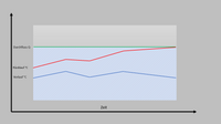
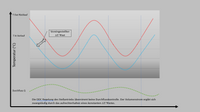
To optimize the efficiency of cooling systems, DeltaT control, also known as temperature difference control, is a central feature of this control system. The temperature difference between the supply and return lines of a heat generator is measured. The controller regulates this DeltaT to a specified target value via the volume flow. The goal is to keep this DeltaT at the optimal level possible in order to save energy and stabilize heat absorption in the cooling system. This results in improved process reliability with optimized energy consumption.
Design
The central core of the system is the control system, which communicates digitally via fieldbus via Modbus and also analogously with the control valves of the respective control circuits. Except for the basic version, which includes only one control circuit, a system consists of several cooling circuits that can be individually controlled and configured via the PLC. Data logging of the most important parameters is possible for each individual cooling circuit directly via the HMI with the PLC. Multiple systems are, in turn, grouped into sub-areas. The consumption of individual circuits, systems, sub-areas, as well as the total consumption of the entire system via flow and cooling capacity are forwarded by the PLC to a web server or an internal evaluation system and can be accessed, analyzed, and further processed via specially created web pages and dashboards. Data management via a cloud is also possible. A basic version is also available for just one control circuit.
Hardware
Control Circuit Setup
The sensors for recording the control input parameters consist of only two PT1000 temperature sensors, one located in the inlet and one in the return, and a vortex flow sensor in the return. The digital control valve, also mounted in the return, controls the flow rate based on the currently specified setpoint.

Single or multiple?
The system's major advantage over other flow control systems available on the market is its variability in terms of flow volume and the scalability of the number of control circuits. The control valves can be installed either independently at any location or mounted compactly and centrally via a manifold.

Software
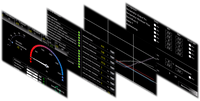
When configuring the cooling system, multiple cooling circuits (multi-zone) can be predefined, with each individual cooling circuit being independently adjustable. This allows individual cooling circuits within a system to operate simultaneously with different operating modes. Equally individual default parameters such as actuating speed, temperature units, flow rate, and cooling capacity are also possible. Glycol mixtures can also be taken into account in the cooling circuits by entering a correction factor. The most relevant actuator parameters can be individually called up using "call functions." Furthermore, the current status of the actuator is continuously monitored and displayed on a separate page. The system is also optionally designed for a dew point monitor to monitor or prevent the formation of condensate on surfaces.
The currently active operating mode of a cooling circuit is displayed in detail and clearly on an overview page. From this overview, you can switch to different sub-areas and functions. Alarm limits can be specified for all involved parameters and activated/deactivated individually. If an alarm limit is exceeded or the actuator reports a fault, the corresponding alarm is displayed via a flow banner. Digital output signals can also be activated here to communicate with an external control system when an alarm is triggered.
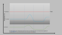
All parameters can be variably and individually displayed graphically using curves in a trend graph. Cyclic recording of these measured data is also very easy. Here, too, the appropriate unit can be freely selected. The recordings can be saved in either native or CSV format. A data management system allows sample data sets, data tables, and alarm logs to be exported to other storage media (SD card, USB stick). Importing externally stored data sets is also very easy using this data management system.
Operating modes
Flow Control
With flow control, the desired volume flow is specified via a setpoint. The following units can be selected: l/h, l/min, gpm, and %. An add-on calculation program can be used to calculate the minimum flow rate to ensure turbulent flow, taking into account the temperature and density of the medium and a specified minimum Reynolds number. This calculated minimum flow rate can be monitored during control operation.
Performance Control
In performance control mode, as already described for volume flow control, a desired setpoint is also specified. The following units can be selected for the setting: Temperature: °Celsius, °Fahrenheit; Energy: kW, kBTU/h.
Manual Sider
Using the graphical slider or a numeric input, the target valve position is specified via the HMI as a percentage of the specified design flow. The corresponding flow rate is determined by the valve size and its design flow.
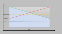
Delta-T Limitation
System efficiency can be improved by defining a minimum DeltaT value. If the currently measured DeltaT value approaches the specified minimum DeltaT limit, the control valve closes to allow the temperature difference to rise again. With dynamic heat input, this reduces the average total flow rate of the cooling medium. Depending on the cooling water supply setup, the flow rate reduction can have a positive impact on energy consumption and overall pumping performance.
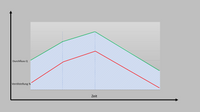
Delta-T Control
With DeltaT control, the control valve processes the current difference between the supply and return flow as a process value. The difference from the previously described control types is that the volume flow is the result and is not included as a control parameter in the calculation. The DeltaT is the parameter used to approach minimized volume flows in order to save energy. In applications in the plastics processing sector, critical quality characteristics that could be particularly affected by warping or shrinkage are observed. Depending on the cooling water supply setup, the flow rate savings can have a positive effect on energy consumption in the overall pumping capacity.
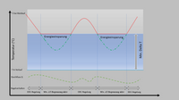
Min. TReturn-Limitation
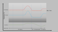
A minimum return temperature is ensured. The control valve begins to close if the user-defined minimum return temperature is not reached. Application examples: To improve chiller efficiency and ensure the correct supply temperature for cooling systems, a minimum return temperature can be specified to prevent a drop in COP and thus the low Delta-T syndrome.
TReturn-Control
The actuator ensures the defined minimum return temperature. To achieve the minimum return temperature, the valve opens or closes until the specified value is reached. This option can be selected to improve cooling water efficiency and ensure the correct inlet temperature, also preventing the DeltaT value syndrome.